Thursday, July 11, 2013

Springfield hanger, HO Scale

Although the 3d Printer is on the fritz, and I have to call tech support again today, it does give me time for another post

This is a Google Earth picture of some of the airplane hangers at the downtown airport in Springfield, MO.  They kind of look like modified Quonset huts. I want to model a small airport on my model railroad, and I really liked the look of these hangers.  And they certainly look like they would fit in my late 1940's era model railroad layout.
Here is a drawing of the full model.  If I were to print it in a single print, it would have lots of support material, particularly in the interior.  On top of that, the layering would be horizontally across the structure.  We want the layering to run vertically, since any weather we would do to structures would run vertically.  Rain does not run sideways.

This how I printed it.  I cut the building up so that any layering would be in the vertical position when the building is assembled.  The only support material needed will be what every is needed to hold up the ribs, which in this position are horizontal.
This is the building primed and test assembled.  The door track will be made from styrene shapes.  


Here is a series of pictures of the finished airplane hanger in HO scale.  I also printed the foundation, and mixed both stone and concrete block, as I wanted it to look like the foundation has been repaired.
The airplane is a long out of production model from AHM.  Now that I know it will work, I would like to measure the real hangers, and print on that is true to the prototype.


Saturday, July 6, 2013

Kitforums.com diorama, Part 3, HO scale Model Railroad Diorama

Since I am blogging mostly about 3d printing as it applies to my model railroading adventures.  Let me first state that the reason I have not blogged in a while is because I have been busy modeling (printing).  A lot of modelers take the summer off for outside activities, I, however, watch the KC Royals, and model.  The 3d printer, an Afinia H Series, seems to have broken, so I will be talking to tech support on Monday, and, I would assume the extruder is broken, and I will need to ship it to MN for repairs.

The last section in this 6" x 6" diorama is the three window wide four unit apartment building.  This is a picture of the first drawing of the front of the building.  For this project, I decided to model the back, but in general, they are the same, except I am adding wood decks to the upper floors on the back.

This is the drawing, similar to the print file, that I used for the top floor.  Due to the print time, each floor was printed separately and glued together later.  This top floor alone took over three hours to print.  So figure three hours per floor, plus the windows, the unit probably took over 12 hours to print.

Here is a good shot of the front giving a good view of the detail in the blocks and the foundation.  A lot of this detail will not be so visible once the decks are installed.

From this higher angle, we can see the open hatch for the roof access stairs.  The roof access stairs and hatch are a one piece print, an hour and twenty minute print.

I will have more on this project later.  The entry was originally due on July 4th, but the deadline was extended, so I have added several details, some 3d printed.

Sunday, June 2, 2013

Kitforums.com diorama, Part 2

Ladies and gentleman, if you are a model railroader, you should be a member of kitforums.com.
I you like to build craftsman kits, you should be a member of kitforums.com
Join, introduce yourself, and tell them I sent you.  They won't hold it against you.

In this entry, I am going to cover the 3d printing of the middle unit in my row house diorama build for the kitforums build challenge.  This is HO scale, and the final diorama will have some railroad track, as that is required for this build challenge.  I like build challenges, they give me a deadline, and I actually have some chance of finishing something. 

This is the original concept drawing.  I made several changes, but I did stay with the same general style. 

Here is the roof as it looks when it is removed from the printer. Note the support material for the door area, but also note there is none needed for the roof slope.


The added parts, all 3d printed, are the railing, the chimney and the sliding door.  The railing was printed in three pieces and solvent welded together.  I would not do it again, as with all the design time, and test print or two, and the sanding the assembled pieces, it would have been much easier to have built it out of styrene and strip wood.  The bricks in the chimney are standard 3x8 bricks, and, by the time I designed in mortar lines, they did not print particularly well.  Some areas are pretty much melted together, and the individual bricks don't show well.  I have not tried it, but I think making them an inch over size would probably fix the issue. 
 
I had test printed lap siding on another project, but with the side laying flat.  The print layers was too visible, and not acceptable, at least to me.  I printed this standing up, just as you see it.  There was a lot of support material needed to hold up the lap, but all in all, the layering barely shows.  However, after I got it all done, it occurred to me that printing it upside down would have eliminated any need for support material for the siding, so next time.....


On the masonry structure, the windows and doors are set back in the wall, where as, on wood sided structures, the windows have a casing that is lapped over the siding.  Printing that lip is not hard, but when the masonry windows just slipped right in place (okay, a little filing, but it was easy), I designed the openings in the building to be as large as the outside of the window casing, and made the window the full thickness of the wall plus the amount of projection needed.  In this picture I have the windows set in at an angle, and you can see what I mean.


Here I have added the roof section to the building and also printed paper shingles.  Also the windows and door have been solvent welded in place.


Here is a view with the window glass and window coverings installed.  Some of the coverings are printed on paper, and glued behind the glass, and some are printed on the glass.  The glass, in all cases, is transparency film.


This is the drawing that was used to print many of the items in this structure.  You can see from this how it was assembled.  Not included in the drawing, but still items I designed and printed, are the porch, the railings, both for the roof walk-out and for the porch, and the sliding door.  This building was designed just for this diorama, so no other walls were added.

The next entry will cover the third, and last building in this diorama. 

Saturday, May 25, 2013

Kitforums.com diorama part one

kitforums.com is having a diorama contest, and I will have several blog entries on the 3d printing portion of the project...this being the first.  For HO scale, the contest is limited to 36 square inches, and I went the simple route, and did mine 6" x 6".  The rules were pretty simple, and can be viewed at kitforums.com should anyone really care. 
My concept was to model the back of three townhouse/row house units that backed up against the tracks, this being the first concept drawing.  The blog entry will cover the right most unit, the unit features a metal standing seam roof, and a dormer.

This is one of my early drawing.  My main interest was to learn more about 3d printing model railroad structures, and getting these done in time to use in clinics I am presenting at the Mid-Continent NMRA in a few weeks. 

As is normal on a new design, it takes several attempts to get everything correct to print.

Here is the roof sections in a trial assembly. 

This was printed in several pieces,  The main walls were done in three sections, foundation, first floor and second floor.  They could have been printed at one time, but the length of time to print it was prohibitive for me.  The top floor alone took over two hours to print.

Each door and window is an individual piece, although they were all printed at the same time.  The roof and dormer is made up of three pieces, plus the window, and then the steps are one piece.
  
     In order to form the blocks, I actually drew individual block, and they are each printed separately.  But, because they are printed touching each other, the melt together a little.  In this case, I used one of the possible negatives of this type of printer to my advantage.  This does add to the print time, but while the wall is printing, I work on some other project. 
     I used clear transparency film for the windows and printed the blinds on paper.  Someone on kitforum had a pdf I downloaded of blinds, and they printed out well.
Next time I will cover the middle unit.

Monday, May 20, 2013

Slab Siding Cabin update


I did not like the pictures in the previous post, so I took some better ones.  This is just a temporary roof, as I plan on installing BEST "wood" shingles.


I will obviously adding a post to the corner to hold up the porch roof.  Also a foundation.


Thursday, May 9, 2013

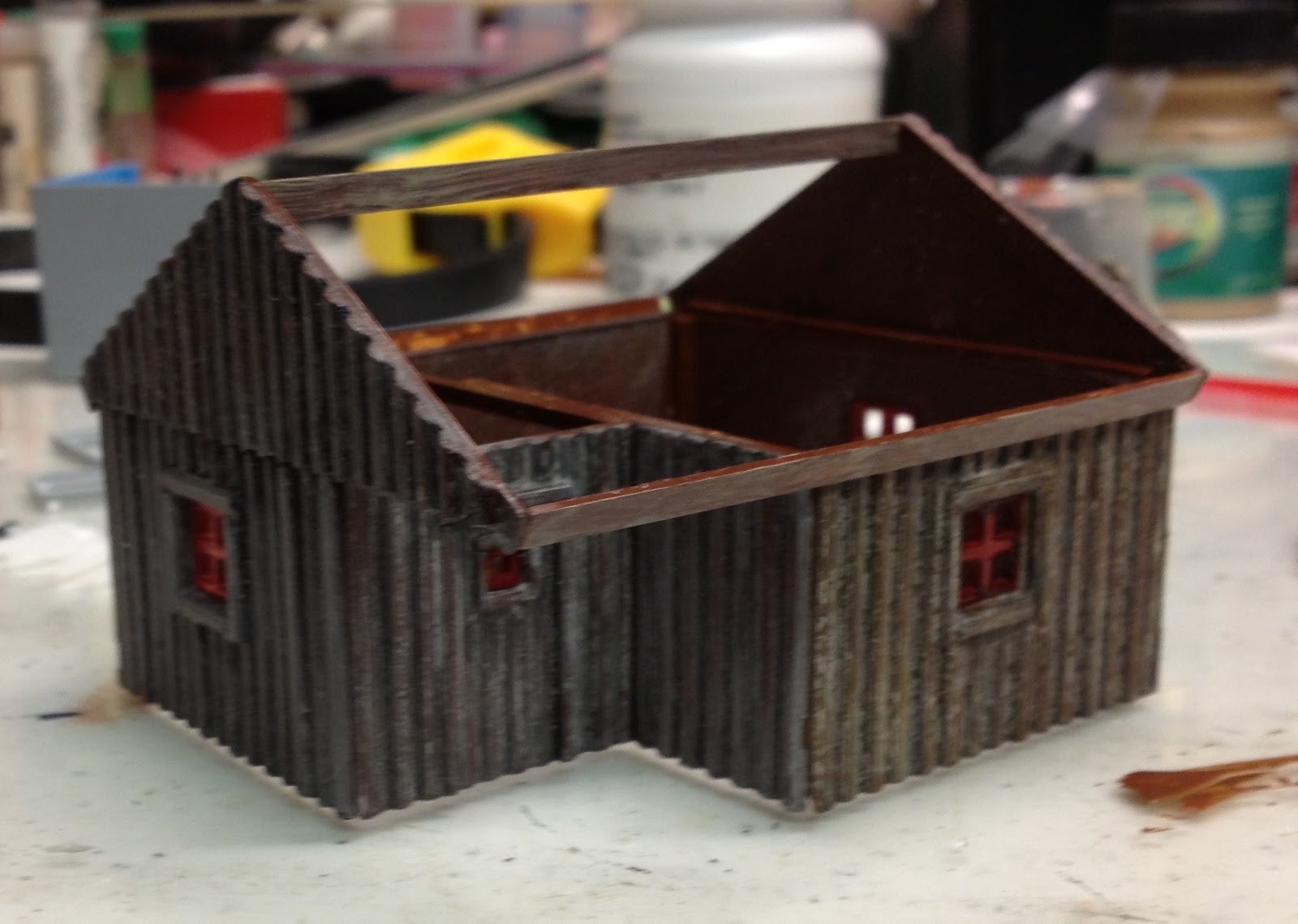
Slab log siding on cabin, 3d Printed, HO scale

This idea came from an article in the Short Line and Narrow Gauge Gazette, July-August, 2008. I would show a copy of it here if it wasn't for those pesky copyright laws.

As usual, I did the drawings in sketchup, then converted the drawings to stl files for printing.


Here is a view from the front.  I only drew one gable end, as the same size will work on both ends.
 
When it came time to print it, I decided it would be be to print the sides laying down.  This, hopefully, would take advantage of the layering that is just part of the printing process.  I thought, and it turns out, rightfully so, that the layering would give me some vertical graining.
 
Here is the front wall, which was my test print.  I painted it with a dark brown, the weathered it with washes of gray and black India ink/alcohol.  After several coats, I ended up with something that would work.
 
This is one of the few times where the test print worked, and I did not have to redesign and reprint before moving on to the full project.  Actually, if I did it again, I would handle the structure corners differently.  I mitered them, most with a shoulder miter.  Since the printer is extruding ABS plastic at 250 degrees Celsius, everything has a slight rounding to it.  Because of that, the shoulders have a fillet in them and really do not allow the corners to fit tight without some carving.  It is easy to carve, much easier than metal castings, but it I did it again, would make the corners square.

As the material is ABS, it will solvent weld with Methylene Chloride.  Also, you can glue styrene to the ABS.  I used styrene for bracing and roof supports.  Obviously, I am going to install a roof, and add a rock foundation.  The foundation will probably be printed, but I will cover that, at a later date.
I plan on using this as the office for one of several logging operations on the planned HO model railroad.

My goal, for the blog, and for my model railroad hobby, this year, was to do enough modeling, and find enough time, to do a blog post every week.  I am way behind, but I am going to try and catch up in the next two months. 

Saturday, May 4, 2013

Outside entrance stairs for HO Scale structures, 3D Printed on the Afinia

Wow, I am getting way behind on my posts.

This is one of many items I thought I would print at shapeways, then I checked the cost, and said no.  But, when I got a 3d printer, the cost went back down, and I have now designed several different types or styles.  This is exactly why I wanted a 3d printer to use in model railroading.  Structures and larger parts are quite economical.

This is an overview of the stairs I have printed so far.  Some of these have a few parts added, and all have either primer or an alcohol and ink wash on them to show the details.


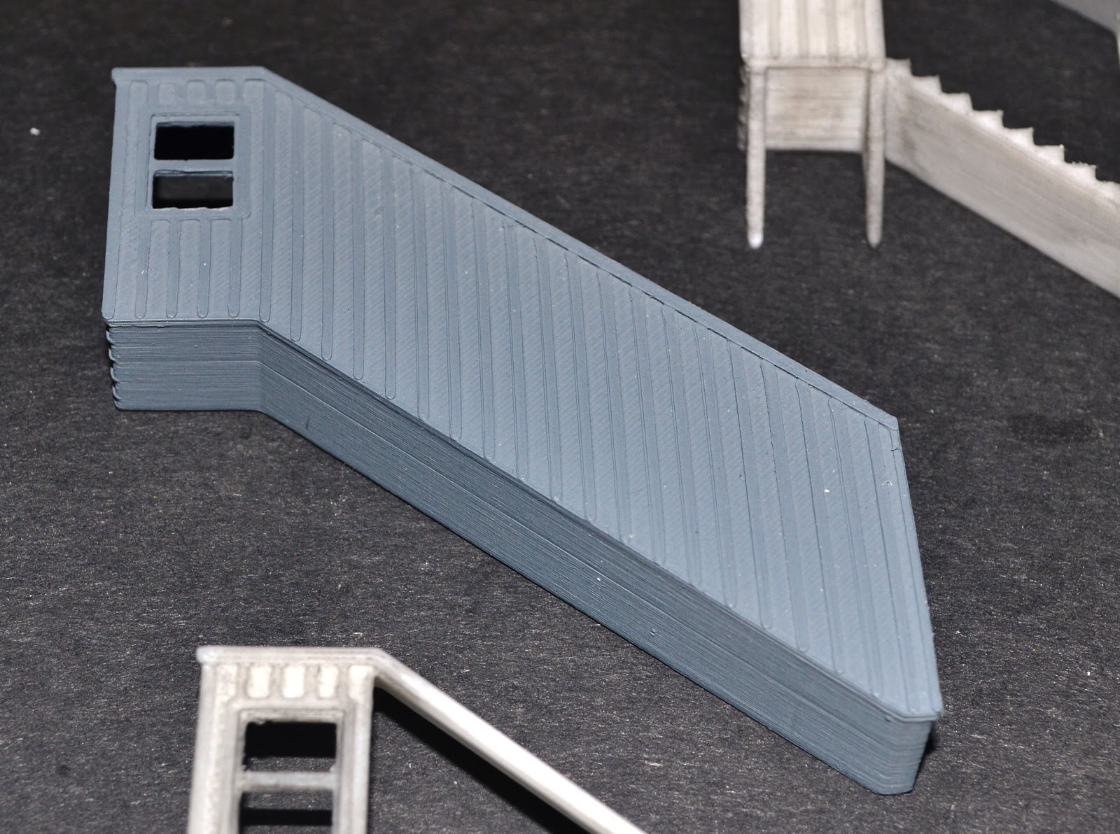
This what the stairs look like as they come off the printer, except the styrene uprights were added at this time to give support to the structure as it is removed from the printing platform, and as the raft is removed.  The raft is the plastic extruded under the part that adheres it to the printer base plate.  Also in this view, you can see the support material on the near end.  I looks like crap, but is will peel off easily, as it is only there to provide support for the battens that were printed horizontally on this side/
 
Viewing from this end, we can see the support material that holds up the window wall. This will also have to be removed, but being a small area, it is usually easy to do.
 
Here is a totally enclosed stairway, which is my favorite. 
 
The only issue with this print is the amount of support material that need to be removed.  From this view, you can imagine the amount of material that it took to support the wall being formed. 
 
It really paints up well, and with a little touch up will fit many a structure on just about any era model railroad.

On the inside, however, you can see the damage I cause when I removed the support material.  Since it is up inside the piece, no one will ever see it, but still is can be an issue.  I have done some web research on this problem, and one suggestion was to pause the print once the support is built, but before the final part starts to print.  You have to be watching really careful to catch it at the right moment, and know how many layers of raft are put down on top of the support material before the final object starts to print, BUT if you catch is at that moment, pause it, spit on your finger (no, I am not kidding), wipe the spit on the raft, and continue the print, the raft peels of MUCH easier.  Sounds kind of stupid, but I have tried it several times now, and it works.


The vertical and angled pieces are styrene, solvent welded to the ABS that was printed.  I add these before the part is removed from the rafts, as it makes the part more stable, since without these pieces, the roof and stairs are only connected at one end.

I am working on a three building background diorama for a build contest at kitforums.com, and I have several other projects that I should be posting some pictures in the next week.  I also have three clinics on 3d printing I need to put together for the Mid-Continent Region of the NMRA that is coming up in June.  More on model railroading and related 3d printing soon.